

I’m pleased to announce that Building the Wingnut Wings Fokker D.VII in 1/32 Scale has just been updated to v1.4 with the addition of some revised text on Page 49.

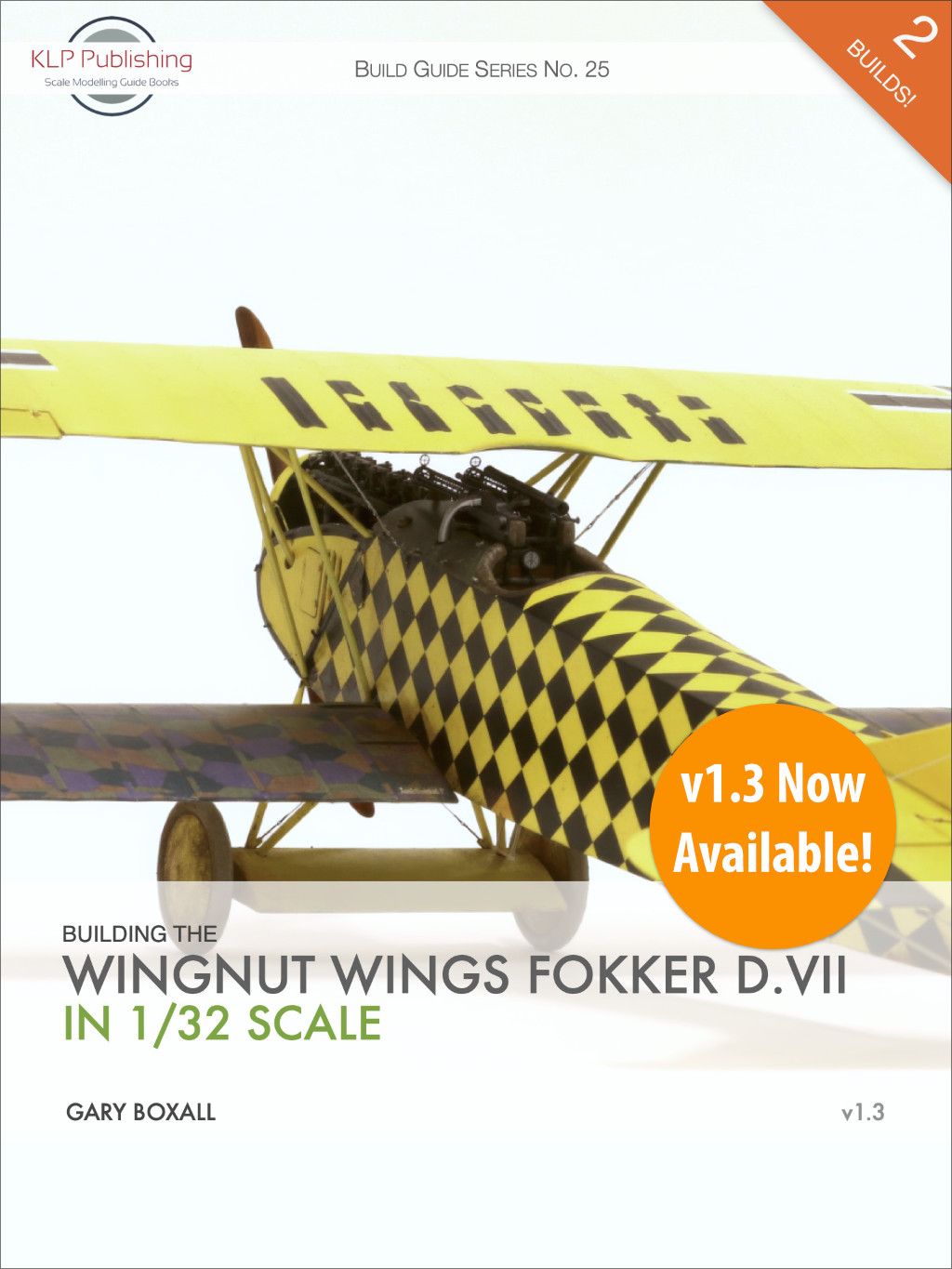
Building the Wingnut Wings Fokker D.VII in 1/32 Scale
In this 382-page eBook, Gary Boxall builds not one, but two Wingnut Wings Fokker D.VII kits in 1/32 scale. The first and most extensive build sees Gary detailing, modifying, and improving the kit to produce Gotthard Sachsenberg’s brightly-coloured machine. The second build leverages the first, and focuses on what it takes to produce a post-war Dutch version of this famous WWI aircraft. We’ve also included our usual Appendices section, covering available aftermarket and reference material.
v1.6 Now Available!
Note: all our prices are in Australian dollars.
This is free for all existing purchasers. And of course, new purchasers will always receive the latest version of any of our books. You can check the version number of your previously-purchased copy at the bottom of the Copyright page (iii), or on the front cover to the right of the author’s name.
In order to obtain your free update, simply re-download the book using either the original download link in your Order Confirmation email, or log in to your KLP account and download it from the Downloads section of your profile. If you don’t have either, please contact me and we’ll sort it out.


You must be logged in to post a comment.