At the end of Part 9, we had the basic paint job done, and were ready for some painted-on markings and decals. Let’s get that done, and get this build over the line!
Since I had planned to paint the fuselage codes and serial numbers, but use decals for the national insignia, the first task was to get a nice gloss coat down in preparation. I appreciated that the whole gloss before decals thing is a contentious one on the modelling Internet these days, but I like to do it anyway as a bit of a security blanket. And the Model Master Olive Drab enamel paint I used had an especially flat and chalky finish.
The national markings are from a Fantasy Printshop set, but were a little bit brittle, so I experienced a bit of cracking here and there. The red demarcations on the flaps were masked and painted. You’ll note that I also painted the base of the antenna on the tail silver.
Next up, the fuselage codes were masked using the set I created and cut earlier using the Silhouette Portrait, and airbrushed with SMS White:
The aircraft name and a handful of stencil decals came from the kit sheet. They weren’t in great shape, so I kept their usage to an absolute minimum. There’s a bit of silvering and some wrinkling to deal with, but nothing a bit more decal solvent didn’t sort out.
The serial numbers were masked and sprayed next, along with fitting the landing gear and prop. A flat coat chased most of the silvering away:
At this point I thought I had an easy ride to the finish line, but guess which dope forgot to remove the interior windscreen masks prior to gluing it into place on the fuselage… I made a right mess getting them out, and managed to knock the gun sight glass off in the process. No way of getting it back in, but at least I managed to remove most of the adhesive residue from inside the windscreen, and hide most of the scratches I made.
One last thing to address before I could call it done: the sliding portion of the canopy. It didn’t really fit properly in the closed position, so I’d have to pose it open (which was the plan all along). But it doesn’t sit properly when slid back, either! As the fuselage narrows towards the read of the cockpit, the front of the canopy obviously doesn’t pinch in to accommodate this, and so just drapes down over the fuselage. So I added a pair of short lengths of styrene strip to act as supports for the front of the sliding canopy:
These did the job admirably:
I painted them Interior Green to get them to blend in as much as possible, and they don’t really stand out on the finished model. You’ll note that I also added a rear-view mirror to the top of the windscreen, which I borrowed from the Tamiya kit, after determining the correct style.
After fitting the final fiddly bits, it was finally done!
Thanks to everybody for following along, and I hope the result meets with your approval. If you’d like to read a much more in-depth account of the process, check out my build thread over on the Large Scale Planes forums.
When we left off at the end of Part 8, we were just about to embark on the painting stage, after getting a solid coat of primer down (Mr. Finishing Surfacer 1500 Black). I decided to start with the wheel bays:
Now I appreciate that Mustang wheel bays weren’t really interior green, but out of expedience, this one will be. I’m also going to fit the inner clamshell doors in the closed position to help hide as much of them as possible, since they’re totally inaccurate anyway.
I also decided that I would try painting the national insignia first, using the Montex mask set I had purchased. The reasoning here is that this would make it easier to hide the white fringing that you often see with painted markings that are laid over a white base layer. This didn’t go well however, as I discovered I’d put the upper wing insignia on the wrong side:
Luckily I had made backup versions of the insignia masks using my Silhouette Portrait cutter. But even after correcting this rookie error, I was far from satisfied with the results, and repeated attempts gave me issues that ranged from distorted insignia to paint lifting, and even one that turned out to be well oversized! In the end, I reluctantly decided to resort to decals for the national insignia, but paint the codes and serials.
Skipping all the grievous updates that show my stupid mistakes, I finally arrived at a successful application of Mr. Hobby H-53 Neutral Grey on the undersides:
This was followed by Olive Drab from an ancient bottle of Model Master enamel paint I had in the stash (the only example of such a colour I had):
In each case I applied the paint with a mottling technique, designed to give a subtly variegated effect. I think I went a little too far with it, and the end result is a little too uniform, but it’s effective enough.
It was at this point that I took another long break from the build, and it found itself back on the Shelf of Doom. By the time I returned to it in early 2024, I was on a mission to just get it done, so things accelerated rapidly, and it was all over pretty quickly. But we’ll deal with that in the next update! It’ll be a longer one, but we’ll bring this thing home in the process.
It’s been a long time since I published Part 7 of this build log, with the model once again finding itself back on the Shelf of Doom—even if only temporarily. It was, eventually, returned to the workbench and finished off earlier this year (2024), so I’ll endeavour to catch you all up in as few posts as possible!
The build had now evolved to the point where I felt it was safe to put a coat of primer down, and in this case it was Mr. Finishing Surfacer 1500 Black, thinned from the jar and applied with an airbrush:
I also added some token canopy rails from Evergreen styrene strip—partly to help hide the joint problems in that area, and partly because it’s very plain, and will be highly visible with the canopy slid back:
The other thing I decided to do is something I should have tackled way earlier in the build, and probably prior to assembling the fuselage: represent the AN/APS-13 tail warning radar antenna on the fin. I figured this wouldn’t be much of a problem…until I tried to do it! My initial idea was to simply drill holes on each side at the appropriate locations, and insert suitably sized wires to do the job. I’ll spare you the gory details, but after a long series of ham-fisted mishaps, this approach proved to be an abject failure, and mostly due to poor planning and execution on my part. Suffice to say I broke a good half-dozen micro drill bits in the attempt.
And then I had a bright idea! (Anybody worried, yet?) The Tamiya kit has this antenna array as a single piece of photo-etched stainless steel, so I thought I might be able to use it here on this build, and save me some pain. So I set about joining up my ill-fated holes to form a pair of slots, into which I could insert the Tamiya photo-etched part:
I secured it initially with a liberal dose of Mr. Cement S, which melted the plastic to the tiny PE and grabbed it nicely. I then flooded the area with some thin CA. The next step was to pack out the nasty gouges on each side with some Milliput:
It took a bit of effort to clean the area up and smooth it out, but at least this important detail was taken care of. And of course, I put the antenna in backwards!
After another application of primer, it at least looked passable:
Like much of what I do at the workbench, my attempt to use primer to build up the mounting plate for the fin antenna didn’t quite go to plan:
At least the other side was better:
The sliding hood was masked off inside and out using the Montex masks. These required some additional help in the form of liquid masking fluid—in this case, Mr. Masking Sol Neo. I’m not a huge fan of the stuff, but at least it’s easy to get off.
If I had any doubts about having the canopy open on this one, a proper test fit with the token slide rails in place shows that the sliding hood wasn’t tall enough to meet the canopy anyway:
This brings us up the painting stage, which we’ll take a look at in Part 9. Stay tuned!
When we left off at the end of Part 6, I’d just finished preparing the kit’s windscreen, having decided to use it in preference to the Squadron vacuform part. The next step, logically enough, was to glue it into place and deal with the inevitable seams with some Mr. Surfacer 500 dabbed along the join with an old paint brush:
This was allowed to dry for 24 hours, and then the excess was cleaned up with a cotton bud moistened with Mr. Color Thinner. A quick spritz with Mr. Finishing Surfacer 1500 Black revealed that some additional work was required, which at this stage is still a work in progress! (In the photo above, you can see that I’ve assembled the kit’s sliding canopy, but its purpose here is purely to protect the cockpit, as it will be replaced by the Squadron vacuform component.)
Speaking of the Squadron vacuform canopy, I decided now would be a good time to tackle the sliding hood, which is a vast improvement over the clunky two-piece kit solution. Having already removed the windscreen from the backing sheet, I trimmed around the sliding hood with a sharp pair of scissors:
After a bunch of careful work with scissors, a hobby knife, some wet’n’dry and some sanding sticks, I arrived at this:
And a quick test-fit onto the fuselage:
It sits slightly low against the windscreen, and the easiest way to deal with that is to pose it open! However, this leaves me with the same problem I had with the vac windscreen: the material is too thin. I decided to bulk out the forward frame with some styrene strip:
The next steps will be to mask this piece inside and out, and get some black paint on the internal framing. After that, whatever internal detailing I can be bothered with will be added! But that’s for another update.
At this point I figured I’d turn my attention to the main landing gear, and the first task was to prepare the True Details resin wheels:
This is an old school set that features this company’s infamous exaggerated tyre bulges, so once they were removed from their casting blocks, I set about reducing these bulges to a much more realistic level:
The moulded-in flat spots are enough to convey the required impression of “weight on wheels”, and are in fact enough to allow the wheels to stand upright on their own. Painted up with the aid of wheel masks from the Montex set, they look the part:
This left the landing gear legs to do, each of which required some brake lines to be added. My first attempt was a total failure, so I stripped everything off and started again, finally arriving at the result below:
So we have some guitar string, some lead wire, some ANYZ braided wire and 3D-printed connectors, along with some heat-stretched cotton bud stems, and a few bolt head details from styrene rod. This was a challenge for my fading eyesight and complete lack of finesse, but I got there in the end. The tyre hubs have also had an oil wash in the interim. Note that I pre-painted and masked the oleo pistons prior to adding the brake lines. This made the masking tape quite difficult to remove after the fact!
It was all worth it, however, as the fully painted final result came out quite well:
The data placards came from the Eduard exterior detail set. Decals would have been a better solution, but I wanted to give these a try, and am happy enough with how they turned out.
And this brings us to the end of this update! Stay tuned for Part 8, where I hope to finish off the sliding canopy hood, and finally start the painting phase.
In this 152-page eBook, renowned UK modeller Iain Ogilvie tackles the Revell 1/32 scale He 219A-7 kit, finishing it to a superb standard. Along with plenty of hints and tips throughout the build, Iain navigates a simple but ingenious way of correcting the kit’s major flaw: misshapen engine nacelles that are set at an incorrect angle.
This update fixes a few minor flaws, and updates the links for the Barracuda products included in the Appendices.
Existing purchasers are able to access the updated version for free. Simply log in to your account (or use your original download link) and re-download the book from the Downloads section of your profile. If you don’t have an account or the original download link, please contact me and we’ll sort it out. And of course, new purchasers will always receive the latest version.
To be sure you have the latest version, you can check the version number located at the bottom of the Copyright page (iii):
I last posted an update for this build back in June of 2022, and since then, things have been a little quiet at the workbench. I’m pleased to report, however, that there has been some recent progress, so let’s catch up!
After having finished the propeller, I started the process of painting the main airframe, and this began with the chequered nose. After masking off the exhaust stacks, I used the same SMS RLM04 yellow that I’d used on the spinner to lay down a base coat around the nose:
To create the chequers, I scanned the kit decals, imported them into Silhouette Studio, and using the auto-trace function, turned them into cut files that I could output to my Silhouette Portrait cutter. This was a somewhat fiddly and time-consuming process, but the results were worth the effort. Once cut, I applied the chequers to the model, masking out the yellow squares I wanted to keep:
This was followed by a quick dose of SMS Red, put on without any additional thinning:
And the result:
As expected, the vinyl masks didn’t conform all that well around the chin intake area, leaving things a bit untidy:
After applying the necessary touch-ups, I gave the whole area a gloss coat to protect the paint from subsequent masking. I couldn’t resist a test-fit of the prop while I was at it!
Of course, we’re a long way from the painting stage just yet, as I need to deal with the canopy—and in this case, it involves the Squadron vacuform replacement, which is far superior to the kit part. But it also comes with all the challenges that vacuform canopies present in terms of cutting them free of their backing sheets!
With older kits especially, I generally like to attach windscreen parts prior to the painting stage, so that I can address any fit issues and make them appear as part of the airframe, rather than simply stuck on. Below is the Squadron vacuform windscreen test-fitted to the airframe:
The fit is OK, though it will still need some work. I felt, however, that the part itself was actually too thin for scale, which surprised me somewhat. Here it is in comparison to the kit part:
The kit windscreen, while correspondingly too thick for scale, still presented a more credible appearance to my eye, so—much to my own bemusement—I opted to use it instead of the vac part!
Having made that decision, the next step was to mask it, in preparation not only for the painting stage, but also to protect it from any work that might need to be done to ensure a good fit (filling, sanding, etc). On this occasion, however, my normally reliable, tried-and-true methods for canopy masking all let me down! I usually consider myself pretty adept at this task, but this time around, I had to relent and do something I normally don’t do: buy canopy masks! I opted for the full Montex set, which was pretty much all I could find that included canopy masks designed specifically for this kit:
This has, so far, been the only deviation from my original only what’s in the box mantra for this build. Sometimes, you just have to get out of your own way!
So, the windscreen was duly masked up, and test-fitted onto the airframe:
It was at this point that I realised that I’d completely forgotten about the gunsight! A decent resin example is provided as part of the Grand Phoenix cockpit set, so I painted it up, added the reflector glass from clear acetate packaging material, and installed it in place:
Of course, it turns out that it should be black, not light grey, but by the time I discovered this, the windscreen had been glued in place, and it was too late. That’s model building, sometimes! It still looks OK though, I think:
Note that the interior of the windscreen was sprayed black prior to installation.
So, that’s it for this update. Next time, we’ll finish off canopy work, get the main landing gear finished, and make a start on the paint work.
Earlier this year I took the plunge and bought a 3D printer—an Elegoo Saturn to be precise. While I’ve always been an avid aircraft modeller, I’m also a bit of a sci-fi fan, and have had a long-standing interest in building particular vehicles and figures from various well-known sci-fi properties (my recently-completed Bandai Snowspeeder being a good example). The problem is—and particularly in the figure realm—some of these kits are either expensive and hard to find, or don’t exist at all! I can’t tell you how long I’ve searched for affordable examples of some of the old Halcyon and Horizon vinyl kits.
Now I don’t have to.
The advent and maturation of 3D printing has created something of a revolution in scale modelling, and indeed for hobbyists of all stripes. Many fantastic 3D models and designs are available for free or for a modest sum on sites such as Thingiverse, CGTrader, Gambody, and of course many others. And these include many of the subjects I’ve otherwise failed to source as traditional kits.
Adventures in 3D Printing
I started my journey into the dark art of 3D printing with a bust of the T-800 from The Terminator, which came out surprisingly and encouragingly well:
Suitably encouraged, my next effort was another bust, this time of the Iron Man Mk III suit. This is where reality started to set in, with many failed or poor-quality prints, and a botched paint job, before I finally arrived at an acceptable result:
While the failures were disheartening, I was determined to learn from them and power on to the next project, which turned out to be the first 3D model I paid for, Treebeard from The Lord of the Rings:
“Aziz, light!”
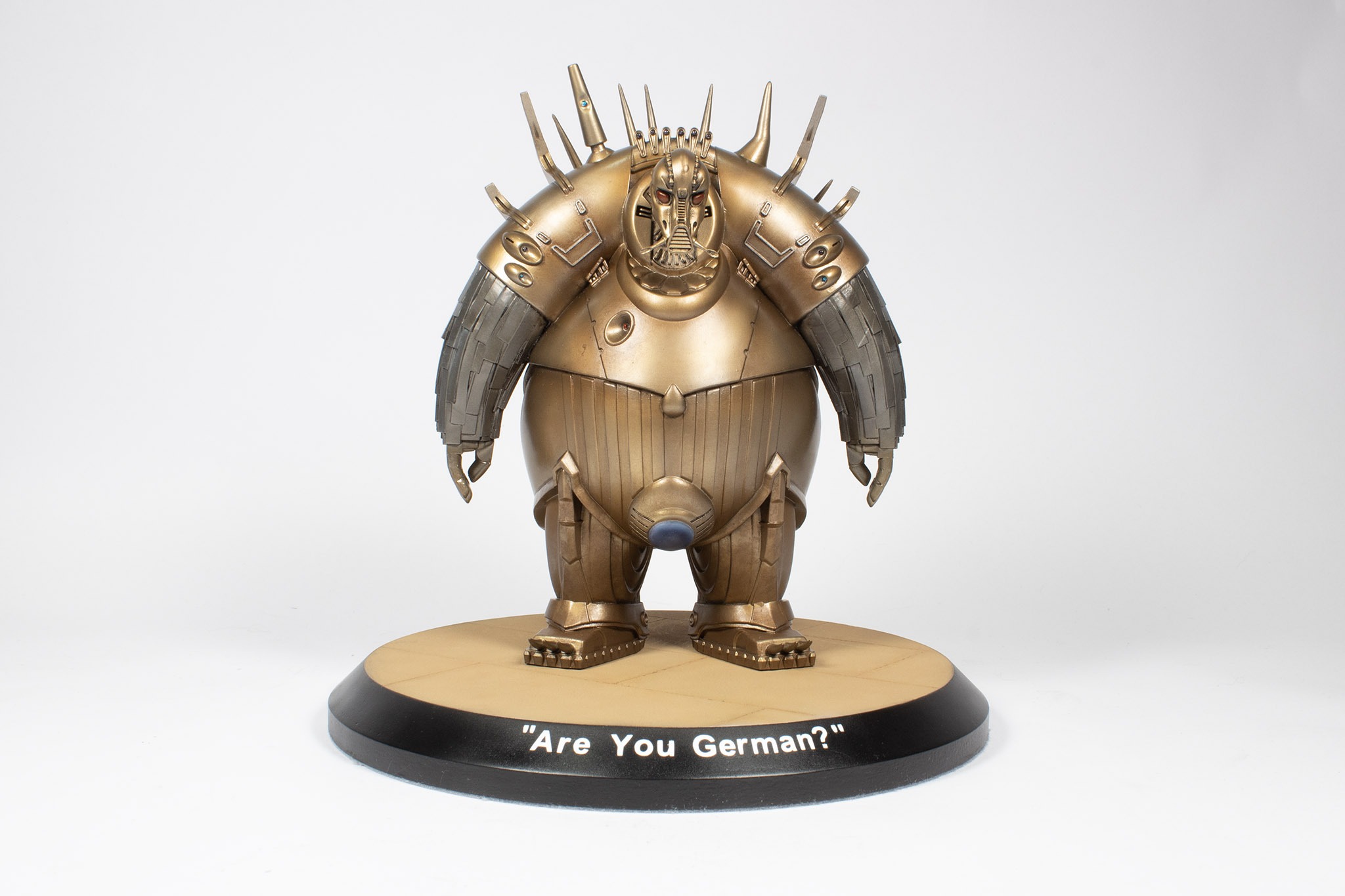
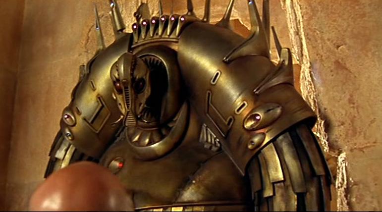
One of my favourite films is Luc Besson’s classic 1997 sci-fi action comedy, The Fifth Element. So naturally I went sniffing about the Interwebs for printable 3D models based on the film. There’s a handful of things around, but I was particularly taken with a Mondoshawan figure I found on Thingiverse. And best of all, it was free! (Mondoshawan’s are the large, rotund, bird-like creatures in the golden metal suits that feature in the opening scenes of the movie.)
The 3D model consists of a number of STL (stereolithography) files that break it into constituent parts for ease of printing and assembly. The head and arms are separate files, while the torso is included as either a single part, or top and bottom halves. I chose the former option, but decided to hollow it out before printing it to save on resin. My first attempt at printing the torso didn’t go well, with one of the legs failing to print at all:
I call him “Stumpy”
The second attempt was much better, but still had an issue with that same leg, producing a toe-tapping version that was amusing, but not really usable:
Which way to the dance?
Before printing the torso a third time (the arms and head printed fine the first time, thankfully), I decided to try removing the happy foot and replacing it with the good foot from the first print, transposing left to right in the process. It turns out they’re not as identical as they look, and it didn’t go well. I’ll spare you photos of the carnage, since they may upset sensitive readers.
Third time’s a charm, as they say, and this time I was lucky enough to have a near-perfect print:
Mostly ‘armless
All this is just to say that, despite the availability of low-cost, high-quality hardware, 3D printing is still a dark art, full of frustrating and expensive failures that can make you wonder why you got involved! There are so many variables to manage in achieving a successful print that it can be a complete mystery as to why one print failed when another did not. I consider myself to still be an ignorant neophyte, with a long way to go and much to learn!
“Time not important. Only life important.”
As it turns out, the arms did have some printing flaws that I hadn’t noticed prior to attaching them to the torso, but I decided to live with them, having had enough of reprinting for this project!
So, let’s take a look at the painting steps I took in attempting to replicate the finish we see on screen. It’s a brassy tone with hints of copper and silver, and is far from pristine, with darker areas of staining and contrast. A challenge! I started with a primer coat of Mr. Finishing Surfacer Black 1500, followed by a coat of SMS Jet Black to gloss it up.
This was followed by a layer of Xtreme Metal Titanium to create a silvery metallic base tone, followed by a very light coat of Xtreme Metal Brass:
Note that I’ve left the arms alone. An oft-missed detail from the movie is that these guys have arms that appear a much darker steel colour than the brass of their main suit, so I wanted to keep a silver colour as a base to attend to this later.
I then post-shaded this with an airbrush using a combination of SMS Advance Copper, and some Tamiya Red Brown with a dash of black added to it:
I also dry-brushed some of the shoulder areas with some Mr. Color Aluminium to bring back some silver tones. I was now starting to get some the reddish tones and contrast I was after. I still needed more, though, so the next step was to break out the oil paints and start doing some weathering. I mostly used Abteilung Burnt Umber, undiluted, and stippled on the model around the panel joins and overlaps, paying particular attention to the waist. I also stippled a heavy layer of the same paint over the legs and feet, trying to create a tarnished patina and tone down the pristine shiny look.
I also applied some SMS Steel to the arms, which were then given a dark wash of black oil paint, with selective raised strips highlighted using white oil paint. I’m not completely happy with the result, but decided to draw the line there. Note also that I made my best attempt to emulate the ‘crotch light’ using an SMS Chrome base, followed by clear blue and purple colours, and some highlighting with more white oil paint.
The final steps were to paint the eyes with Vallejo Red darkened with some black, paint the suit lights using various clear colours over some chrome applied with the new paint markers from SMS, and highlight the raised frames on the shoulder with a silver pencil. Done!
Late in the painting sequence I decided that Mondo was going to need a base for stability purposes, so I pulled a craftwood base out of my stash and set about using it to represent the floor of the temple at the beginning of the film.
Stone floor scribed into the woodBevel painted gloss blackConcrete texture paint from a spray canSandy browns mottled over surface, grooves darkenedLettering masks cut with Silhouette Portrait
While the printing process to produce this model was frustrating at times, it still knocks me out that I can press a button on a machine in my hobby room and produce such marvellous objects. And I’ll certainly be producing many more! But the real fun was in the painting process, and even producing the base was quite enjoyable. I really like the result, and I hope you do too!
It’s been a while since our last update on this build, and sadly, things have been moving rather slowly. I think as modellers we share a tendency to start finding other things to do when a build starts getting tricky, or when it gets to those bits that we just don’t enjoy doing. In the case of this build, I was stalled on needing to create masks for the chequered nose, and baulking at having to deal with the vacuform canopy. So I built a Bandai Snowspeeder instead!
But I’m pleased to report that I’ve finally made enough progress to be worth posting about, so let’s take a look at what I have done. The main focus of my recent efforts has been the propeller, and more specifically, the spinner. The aircraft that I’ve elected to depict, “Butch Baby” of the 357th Fighter Group (44-14798), features a red-and-yellow chequered nose band with a spinner striped in the same colours:
Decals for this aircraft are supplied in Hasegawa’s 1992 boxing of the kit (ST5), but I decided that I’d prefer to paint as many of the markings as possible, with decals being limited to the aircraft name (which I didn’t feel I could replicate neatly with masks), and the occasional airframe stencil. My plan was to take a high-resolution scan of the kit decal sheet, and then using the trace function built into the Silhouette Studio software, produce a cut file that I could send to my Silhouette Portrait cutter to produce a set of vinyl masks. In practise it turned out to be slightly more complicated than that, but we’ll get to that shortly!
In any case, there were no decals for the spinner stripes to scan, so I knew I’d have to do this the old-fashioned way. I started with the easy bit, which was to paint the entire spinner yellow, using Tamiya XF-3 Flat Yellow. But then I had a fancy idea. And that’s where things went a bit wrong!
I thought I’d experiment with a technique I’d used successfully in the past for scribing spinners and other conical objects. This involves taking a blade or scribing tool, and ‘mounting’ it horizontally on some flexible putty (such as Silly Putty, for example), in such a way that the sharp end of the tool meets the part where you want the line. I figured this could work for cutting the central band out of a masked-up canopy too!
Here’s the general arrangement I came up with:
The balsa sheet is to accommodate the central tube moulded into the back of the spinner that protrudes beyond the backplate:
The idea is to simply rotate the spinner against the blade at the required height—starting with the higher of the two cuts—then press the blade handle into the soft putty until you reach the required lower height, and repeat. Using that process gave me this:
Now, you’ve probably already figured out that this didn’t go as well as I had hoped, but it really wasn’t a complete disaster. After applying the red and unmasking, I arrived at this result:
Hmm, not really what I was going for! I did learn some lessons, though, and I’m sure on a repeat try, I would have achieved a much better result. For starters, the knife/putty combination really needed to be on the balsa sheet with the spinner, as I struggled to stop the balsa square from rotating away from the blade. Consequently, I ended up applying the blade force inconsistently, resulting in some areas of tape not cutting properly, while in other areas I actually cut into the spinner.
Overall, though, I concluded this method a fail, and decided to try another approach: one that I’d used before on smaller parts, but not for a multi-coloured object like this spinner. So I stripped it all back to bare plastic by leaving it in a jar of Windex overnight, cleaned up the wounds, and started again.
First, a fresh coat of yellow, this time using SMS RLM04:
This second method involved using a circle template to form the demarcation points, and backfilling the remaining areas with masking putty.
Unfortunately I didn’t have enough hands to snap a photo of the mask in action, but I can at least report complete success:
The red is SMS Red. I did have to touch up a couple of areas, but that was no big deal. Phew!
But of course, I still had to do the prop blades, which were the source of yet more modelling angst. The basic paint job was easy enough: paint the tips yellow (SMS RLM04 again), mask them off, and then paint the rest of the blades black:
The problems came once I’d applied the kit stencil decals. Thick and shiny, I just couldn’t hide the carrier film, despite multiple gloss coats, sanding the edges, and a flat coat:
The blade top right in this photo really shows the thick and shiny carrier film, despite doing “all the right things” to eliminate it.
I could see straight away that the problem wasn’t traditional ‘silvering’: that horrible problem caused by are becoming trapped under the decal. I really had no choice but to repeat my previous treatment process, but with one important change; this time, instead of using a sanding sponge to reduce the thick edges of the carrier film, I used a stiff sanding board of a very mild grit, so that the sanding surface wouldn’t make allowances for the said edge like I suspect the sponge did.
So, some judicious sanding and some heavy gloss coats later, I was pretty convinced I’d solved the problem:
Hmm, shiny!
And the final flat coat to seal the deal, as they say:
Not perfect, but much improved, and certainly good enough for gubment work.
And I think that’s about it for this update! Next time, we’ll take a look at how I get on with the nose chequers, the vacuform windscreen, and the process of painting on the markings.
Inspired by some other examples I’d seen online, I decided to have a go at filming a quick 360° video of my recently-completed Bandai Snowspeeder build. Turns out my old Hobby Tools (Trumpeter) motorised display turntable was kaput, which forced me to purchase a replacement. I wanted something bigger and better anyway, but after a frustrating few hours of reading (mostly negative) reviews, I managed to find just one on Amazon that seemed to fit the bill. Once duly purchased and delivered, I decided to, well, take it for a spin.
Not good! Garbage, in fact. I quickly determined that the main issue seemed to be that the base of the turntable didn’t sit flat on the table, but instead had quite a significant wobble. After taking a bastard file to two of the four moulded-in plastic feet, I was able to rectify the problem, but unfortunately it made no difference to the level of jitteriness exhibited by the Snowspeeder. It seems there’s just too much instability in the stand, exacerbated by the angle I set it at. I need to do some follow-up testing with other types of models, but I suspect anything with spindly undercarriage will produce similar results. My guess is most cars, AFVs, and figures would be fine.
So, disappointed but not defeated, I shall retreat to the hobby room for some more tinkering.
This video—a relative failure though it is—also represents a soft launch of the KLP Publishing YouTube channel. Even though there’s not a lot happening just yet, it would be fantastic—and much appreciated—if you could give it a “like and subscribe”, as they say. I’m also happy to take any suggestions for content you’d like to see.
And don’t forget to subscribe to our blog for future news and updates!
I took this project on as part of my friend Scott Taylor’s #smschallenge2 on The Scale Modeller’s Supply Facebook group. Scott is the proprietor of The Scale Modellers Supply (SMS), purveyor of the fantastic SMS paints range, among other useful modelling tools and supplies. The challenge was to build a Star Wars kit—any Star Wars kit, and kicked off, appropriately enough, on May the Fourth.
Here’s the kit in question:
If you’ve never seen one of these Bandai Star Wars kits in the flesh, you’re in for a treat the first time that you do. They’re really quite amazing, and can literally be built without any glue. The level of detail, quality of moulding, and overall execution of the package is second to none. There are three runners of light grey plastic, one in black, one in translucent red, and a runner for the clear parts that has been stunningly moulded with the black runner!
Despite being essentially a “snap-together” kit, it features some amazing detail and engineering.
Markings are provided as either standard waterslide decals, or child-friendly self-adhesive stickers.
The instructions are in Japanese for the most part, but an English translation is available.
Getting to first base with this kit is a doddle, though there are traps for the unwary—I did manage to screw up the orientation of a couple of parts, however, which is pretty true to form for me!
Note that I raced ahead and glued the rear cockpit cowl in place too early, which would later cause me a bit of an issue!
One of the more challenging aspects of the build is painting the nicely detailed cockpit. If you’re not feeling up to it, decals (and stickers) are included in the kit to provide console details, but I of course chose the hard way!
I used MRP RLM 66 (MRP-59) as a scale black for the base colour, followed by careful brush painting with various Vallejo Model Color acrylics.
The cockpit side consoles were a real challenge to paint, but turned out OK I think. Thankfully, washes and dry-brushing help enormously!
The cockpit seats were painted with Tamiya Deck Tan, and given a heavy wash with Burnt Umber oil paint.
After painting all those small details, I realised I needed better detailing brushes!
The rear cockpit console. Some of the smallest details were actually painted with a toothpick.
The front cockpit console (left) and rear cockpit screen (right). The latter was first painted silver (Mr. Metal Color MC218 Aluminium), followed by a couple of heavy coats of Tamiya X-23 Clear Blue.
While I had the detail brushes out, I also painted the interior of these equipment bays on what I presume are cannon mounts:
MRP RLM 66 for the base colour, and Vallejo acrylics for the details.
Such is the beautiful simplicity of this kit, that once the cockpit was fully painted, the main fuselage (hull?) parts could be assembled:
The rear cockpit hood being clamped back into position after emergency removal!
Of course, this is where my too-early installation of the rear cockpit hood came back to haunt me, as it blocked the rear console assembly from being slid into place! I ended up having to saw the hood off with a razor saw, insert the rear console assembly, reattach the hood (seen clamped after gluing in the photo above), and then blend in the join with Mr. Surfacer 500. Even Bandai kits aren’t safe from my ham fists!
With careful painting, the cockpit really comes to life.
I took a lot of my cues for this build from a 3-part video series by Jon Bius on YouTube, and he suggests leaving the rear section off the model until the very end, whereas Bandai would have you enclose it between the fuselage halves while joining them.
I had a bit of trouble getting it fully inserted properly at the end, so I’m not sure if I would do it that way again.
Another tip I got from Jon’s build is to use the 2-piece canopy solution (rather than the 2-piece all clear alternative), mask the inner clear piece, and then assemble them temporarily for painting and weathering:
Here are all the major assemblies after a couple of light coats of Mr. Finishing Surfacer 1500:
I added little tabs from Tamiya tape to the equipment bay covers, so I could use them a masks while painting, but easily pull them off when I was done.
The black areas were painted first with Tamiya Rubber Black. I decided to keep the Mr. Surfacer as the base colour, as it’s pretty close to what I was aiming for anyway, and will make a good base for the subsequent weathering. I also decided to try the kit decals for all the panel variations, rather than mask and paint them.
Kit decals being applied over a coat of Tamiya X-22 Clear Gloss.
I elected to use the kit panel decals, rather than mask and paint them, just to see how they would work out.
While the kit decals were OK, I’d definitely mask and paint them next time. For starters, the printing is surprisingly coarse, with the dot pattern quite visible close up. They’re also quite thick, and I had to deal with some residual tenting issues around raised details. And the last issue, one of my own making, is that I misplaced some of the underside panels, creating gaps and misalignments along the way. I decided not to apply two of them at all in the end, as there was no way they were going down over the raised details in those areas (I did try with one of them).
Now I could start in on the weathering, which started with a panel line wash.
This was actually the second attempt at the panel line wash, as my first attempt with oils (my usual approach) all but wiped right off completely during clean up. I had to fall back to some AK Interactive Panel Liner, and even then, it’s still pretty patchy. Ultimately I deepened some of the panel lines around the nose that weren’t holding on to the wash, and reapplied it with more success.
While I waited for those initial weathering passes to dry off, I decided to start painting the two pilot figures, base-coating with Fire Orange from the new Infinite Colour range from SMS:
This was followed by a heavy wash of Burnt Umber oil paint, and then a couple of hours of detail painting and decalling, to arrive at the result below:
Putting the ‘pain’ back into painting. The cockpit figures don’t look great in close up, but at normal viewing distances, they seem to do the job.
And back to the final phases of the weathering process, rendered mostly with filters of oil paint and some chipping with acrylics:
The cannon assemblies just click into place, but I chose to glue them down for a better overall fit.
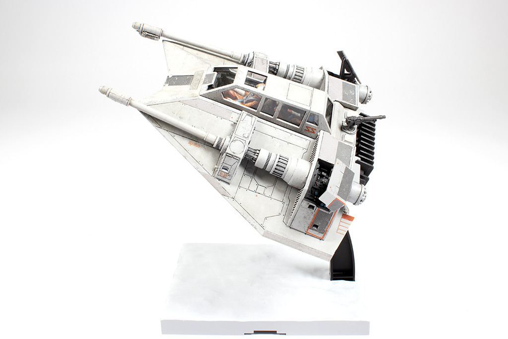
With the weathering complete, final assembly could begin. I elected to use the kit’s display stand for simplicity’s sake, so it was painted up in off-white and black, ready for duty:
Time to install the crew figures:
The final tasks were to paint the inside of the plastic canopy part, along with the rear gun, and then assemble and install both. The gun was painted with RLM 66, given a flat coat, and I mounted the finished model on the display stand at a suitably dynamic angle.
I enjoyed this build tremendously, and am already struggling to resist the urge to crack open another Bandai Star Wars kit immediately! If you haven’t built one, I recommend you do so, and as soon as possible!


You must be logged in to post a comment.